Step 1. Go to Controller - > Interface -> New to
create new interface.

Step 2. Give the interface name and Vlan id and press APPLY.

Step 3. Provide the IP address/Netmask/Gateway to the
interface. Also enter the VLAN id to which the ssid traffic will be mapped.
Map the logical interface to the physical port of the WLC.
DHCP server setting: - Enter WLC’s own address when the DHCP
scope is created on WLC itself otherwise adds external DHCP server IP
addresses.

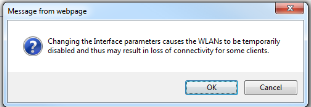
Step 4. Press APPLY to apply the interface settings. You
will get the below warning which says that it can impact the connectivity to
the SSID. Hence we should not change the interface setting during production
hours.
Step 5. Once you press ok, you will get the list of
interface created so far.

Step 6. Go to WLAN ->wlan -> From the scroll Tab on
right side plan, select CREATE NEW and
press GO.

Step 7 Enter Profile name and SSID name and select the
unique ID and press APPLY.

Step 8 Click the SSID ID to configure the other parameter of
the SSID.
Select the interface and radio policy for the SSID.

Step 9 Go to Security
-> Layer 2 security and chose none.

Step 10. In Layer 3 security tab, select none option and press APPLY.

Step 11. Enable the SSID, once the configuration is done.

Step 14 Go to WLAN - > WLANS and check the status of the
SSID.


