Sunday 31 August 2014

What is Fabric module in Cisco Nexus 7000 switches ?

Fabric modules provide connectivity between Supervisor module and line cards. 7k chassis support up to 5 fabric cards.

Fabric cards must be present in all 7K nexus switches to make it work except 7004 as it doesn't support fabric card.

 Fabric cards are hot swappable, it means we can remove it from the chassis and other Fabric cards will take over with any impact to the traffic.

There are two below types of fabric cards available. the migration from Fab-1 to Fab-2 is non disruptive. But both in the chassis for long duration is not recommended by Cisco.

Fabric module version 1 :-

·         46 Gbps per slot.
·         Maximum performance per slot with 5 Fabric modules is 46 * 5 = 230Gbps
·         Not supported in 7009 chassis.
·         Upto 5 Fabric modules are supported

Fabric module version 2 :-

·         110 Gbps per slot
·         Maximum performance per slot with 5 Fabric modules is 110 *5 =550Gbps.
·         Supported on all 7K series.
·         Upto 5 Fabric modules are supported

Cisco Nexus 7000 Supervisor module comparision - Sup1 Vs Sup2 Vs Sup2E

1. Supervisor 1 :-
  • Before 6.2, maximum 4 VDC (3 non default + 1 default ) are supported. 
  • In 6.2(2), Sup-1 also support admin VDC. It gives you the option to either create 1 x default VDC and 3 x non default VDC or 1 x admin VDC and 4 x non-default VDC.
  • Maximum 32 FEX are supported
  • CMP supported.
  • CPU – Dula core Xeon
  • Speed- 1.66 Ghz
  • Memory – It comes with 4GB RAM and upgrade to 8GB is needed for MPLS and VDC features.
  • CPU share not supported.
2. Supervisor 2 :-
  • Maximum 4+1 admin VDC supported. In initial configuration Wizard, we get an option to create admin VDC. If we choose NO, then we can create 1x default VDC and 3 x non default VDC.
  • Maximum 32 FEX are supported
  • CMP is not supported.
  • CPU – Quad core 
  • Speed- 2.13 Ghz
  • Memory – 8Gb
  • CPU share is supported
3. Supervisor 2E :-
  • Maximum 8+ 1 admin VDC supported. 
  • Maximum 64 FEX are supported
  • CMP is not supported.
  • CPU – Dual  quad core
  • Speed- 2.13 Ghz
  • Memory – 32 Gb
  • CPU share is supported.

Note :-
1. There is a license#LAN_ADVANCED_SERVICES_PKG (N7K-ADV1K9)  needed to create more than one VDC upto 4 VDC. Without license you can only use VDC 1 ( admin or  default whichever is chosen in the initial wizard).
2. For Sup 2, " VDC Licenses (N7K-VDC1K9) " License is needed to add license for 4 VDCs and hence can support 8 VDCs. Each license increment the vdc number by 4.

2. CPU share is the way by which we can allocate the specific CPU to the important VDCs.

Cisco Nexus 7000 FAQs

1. What are the 7K model available?
Answer:- 7004 , 7009 , 7010 and 7018

2. Is 7004 supports all Fabric Modules?
Answer:- No, Fabric module is not present in 7004 whereas all other Nexus 7K needs fabric module to work.

3. In 7k, Can we use supervisor slot for line cards?
Answer :- No, we cannot use supervisor slots for line card.

4. Is Sup-1 supported in all 7k models?
Answer :- No, Sup-1 is not supported in 7004 whereas all other model supports Sup-1.

5. Is fab-1 supported in all 7K models?
Answer:- No, Fab-1 is not supported in 7004 and 7009.

6. Can we use  non-XL M1 model in all 7K?
Answer:- No, non-XL model is not supported in 7004.

7. Can we use mix of Fab-1 and Fab-2 in single chassis?
Answer:- Yes but only one fabric version (1 or 2) is recommended in a chassis.

8. Can we use Fabric module of 7009 to 7018?
Answer: No, we cannot use Fabric module of one model to another.

9. Can we create port-channel with one M-card port and other in F-card port?
Answer:- No, it is not possible to bundle M-series and F-port.

10. Is it possible to create port-channel with M-series on one end an other end is F card?
Answer:- We cannot make port-channel with M port at one end and F at other side.

11. Are FCOE and Fabricpath supported on M-series card?
Answer:- No, Fabricpath and FCOE are not supported on M-series line cards.

12. Is Mixing I/O modules on the same side of a port channel supported?
Answer: No, Mixing of IO modules in a port-channel is not supported.

13. Can we configure LACP on half duplex port?
Answer: - LACP does not support half-duplex mode. Half-duplex ports in LACP port channels are put in the suspended state.

14.  Does nexus 7000 series support fragmentation?

Answer:- No, Nexus 7k doesn't support fragmentation and reassembly.

15. Is dense-mode supported on Nexus 7k?
Answer:- No, Nexus 7k only support PIM sparse mode.

Cisco Nexus 7000 Model comparison.


             7004 :-


·         Fabric Module is not present.
·         Sup 1 is not supported. Only supports Sup2 and Sup 2E. 
·         All XL versions of M1series modules, M2 series modules, and F2 series modules are supported. It does not support the F1 series module or non-XL M1 series modules
·         Maximum 2 line card supported, with 2 dedicated supervisor slots which cannot be used for line cards.
·         Maximum BW per slot is 440 Gig.
·         Throughput - more than 1.92.
·         Supervisor Module slot - 1 and 2


            7009:-


·         Only Fab-2 supported
·         All supervisor and line card supported
·         Maximum 7 line card supported with 2 dedicated supervisor slots.
·         Maximum BW per slot is 550Gig.
·         Throughput – more than 8 Tbps.
·         Rack Space - 14 RU
·         Supervisor Module slot - 1 and 2


              7010:-


·         Maximum 8 line card supported with 2 dedicated supervisor slots. 
·         All Sup, Fab and line card supported.
·         More than 15 Tbps throughput
·         Rack Space - 21 RU
·         Maximum BW per slot is 550Gig.
·         Supervisor Module slot -5 and 6


  7018:-


·         All Sup, Fab and line card supported
·         Maximum 16 line card supported with 2 dedicated supervisor slots.
·         More than 15 Tbps throughput.
·         Rack Space - 25 RU
·         Maximum BW per slot is 550Gig.
                      ·        Supervisor Module slot - 9 and 10


Saturday 30 August 2014

Configure SSID with Mac filtering Cisco WLC


Step 1. Go to CONTROLLER - > INTERRFACE -> NEW to create new interface.


Step 2. Give the interface name and Vlan id and press APPLY.


Step 3. Provide the IP address/Net mask/Gateway to the interface. Also enter the VLAN id to which the SSID traffic will be mapped.

Map the logical interface to the physical port of the WLC.

DHCP server setting: - Enter WLC’s own address when the DHCP scope is created on WLC itself otherwise adds external DHCP server IP addresses.


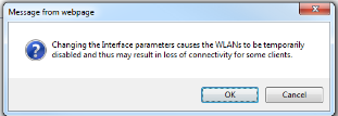
Step 4. Press APPLY to apply the interface settings. You will get the below warning which says that it can impact the connectivity to the SSID. Hence we should not change the interface setting during production hours.


Step 5. Once you press OK, you will get the list of interface created so far.


Step 6. Go to WLAN ->wlan -> From the scroll Tab on right side plan, select CREATE NEW and press GO.


Step 7 Enter Profile name and SSID name and select the unique ID and press APPLY.


Step 8 Click the SSID ID to configure the other parameter of the SSID.

Select the interface and radio policy for the SSID.


Step 9 Go to Security -> Layer 2 security and choose none and select the mac filtering option.

               
Step 10. Go to Security ->Mac filtering and click New.


Step 11 Enter the mac address of the user machine and choose the appropriate profile and interface. Press APPLY to add the mac address.


Step 12. We see the list of mac address.


Step 13. You can delete the mac entry by clicking the blue button and then please Remove.


Step 14. Enable the SSID, once the configuration is done.


Step 15  Go to WLAN - > WLANS and check the status of the SSID.


SSID using WEP autentication in CISCO WLC


Step 1. Go to Controller - > Interface -> New to create new interface.


Step 2. Give the interface name and Vlan id and press APPLY.


Step 3. Provide the IP address/Netmask/Gateway to the interface. Also enter the VLAN id to which the ssid traffic will be mapped.

Map the logical interface to the physical port of the WLC.

DHCP server setting: - Enter WLC’s own address when the DHCP scope is created on WLC itself otherwise adds external DHCP server IP addresses.
 

Step 4. Press APPLY to apply the interface settings. You will get the below warning which says that it can impact the connectivity to the SSID. Hence we should not change the interface setting during production hours.


Step 5. Once you press ok, you will get the list of interface created so far.
  

Step 6. Go to WLAN ->wlan -> From the scroll Tab on right side plan, select CREATE  NEW and press GO.


Step 7 Enter Profile name and SSID name and select the unique ID and press APPLY.


Step 8 Click the SSID ID to configure the other parameter of the SSID.

Select the interface and radio policy for the SSID.


Step 9 Go to Security -> Layer 2 security and chose none. 
 
               
Step 10. In Layer 3 security tab, select none option and press APPLY.


Step 11. Enable the SSID, once the configuration is done.


Step 14 Go to WLAN - > WLANS and check the status of the SSID.


Configure Guest SSID using customized Web login page in CISCO WLC


Step 1. Go to Controller - > Interface  -> New to create new interface.


Step 2. Give the interface name and Vlan id and press APPLY.


Step 3. Provide the IP address/Netmask/Gateway to the interface. Also enter the VLAN id to which the ssid traffic will be mapped.

Map the logical interface to the physical port of the WLC.

DHCP server setting: - Enter WLC’s own address when the DHCP scope is created on WLC itself otherwise adds external DHCP server IP addresses.


Step 4. Press APPLY to apply the interface settings. You will get the below warning which says that it can impact the connectivity to the SSID. 

Hence we should not change the interface setting during production hours for the existing wlan.


Step 5. Once you press OK , you will get the list of interface created so far.


Step 6. Go to WLAN ->wlan -> From the scroll Tab on right side plan, select CREATE  NEW and press GO.


Step 7 Enter Profile name and SSID name and select the unique ID and press APPLY.

  
Step 8 Click the SSID ID to configure the other parameter of the SSID.

Select the interface and radio policy for the SSID.


Step 9 Go to Security -> Layer 2 security and chose none.
  
               
Step 10. In Layer 3 security tab, click on web policy

You can override the global webpage settings as shown in below picture.


Step 11. You can set the global web page and is a optional step. It gives you the option to take the preview of the login page.


Step 12. Select the customize page and press APPLY.


Step 13. Choose the appropriate AAA server.

Please refer to blog AAA server configuration in WLC In order to create new AAA.


Step 14. Enable the SSID, once the configuration is done.


Step 15. Go to WLAN->WLANs and check the wlan status.


Guest SSID configuration in CISCO WLC using internal webpage


 Step 1. Go to Controller - > Interface -> New to create new interface.


Step 2. Give the interface name and Vlan id and press APPLY.


Step 3. Provide the IP address/Netmask/Gateway to the interface. Also enter the VLAN id to which the ssid traffic will be mapped.

Map the logical interface to the physical port of the WLC.

DHCP server setting: - Enter WLC’s own address when the DHCP scope is created on WLC itself otherwise adds external DHCP server IP addresses.


Step 4. Press APPLY to apply the interface settings. You will get the below warning which says that it can impact the connectivity to the SSID. Hence we should not change the interface setting during production hours.


Step 5. Once you press ok, you will get the list of interface created so far.


Step 6. Go to WLAN ->wlan -> From the scroll Tab on right side plan, select CREATE  NEW and press GO.


Step 7 Enter Profile name and SSID name and select the unique ID and press APPLY.


Step 8 Click the SSID ID to configure the other parameter of the SSID.

Select the interface and radio policy for the SSID.


Step 9 Go to Security -> Layer 2 security and chose none. 
 
             
Step 10. In Layer 3 security tab, click on web policy. Check the authentication option and press APPLY.

As soon as you press APPLY it prompts you a warning the Controller will allow the DNS traffic before the client authentication. It is normal.


In WEB authentication, clients gets an IP address before authentication.

Note: - If the DNS servers are not reachable from client then web login page will not be visible to him.

By default it uses the internal cisco page but you can customize it. Please refer to the blog for customize login page.


Step 11. If you want to preview the login page, Go to Security -> Web login page - > chose internal in web authentication type. and press Preview.

You can also modify the Headline and message of the page.

You can also hide the cisco logo in the login page if you want.


Below is the preview of the login page.

Step 12. Choose the appropriate AAA server.

Please refer to blog AAA server configuration in WLC In order to create new AAA.


Step 13. Enable the SSID, once the configuration is done.


Step 14 Go to WLAN - > WLANS and check the status of the SSID.